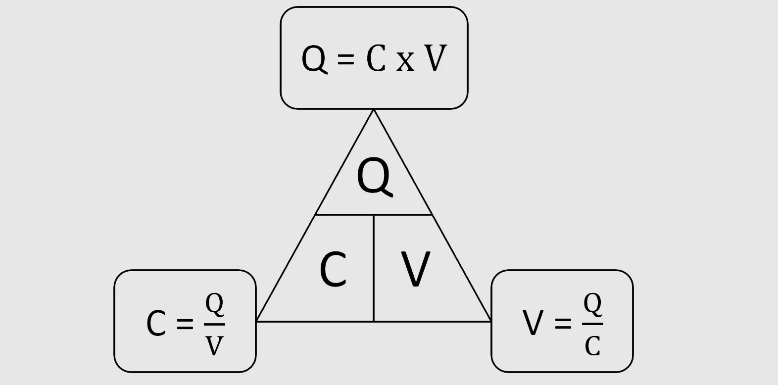
The capacitance formula, C = Q/V, shows how a capacitor stores electric charge (Q) at a given voltage (V). Capacitance, measured in Farads, depends on the material between the plates. Different materials, like rubber or silicon, have unique relative permittivity values, which affect how much charge a capacitor can hold.
| Material | Relative Permittivity (εr) |
|---|---|
| Vacuum | 1 |
| Air | ~1.0006 |
| Rubber | 7 |
| Silicon | 11.68 |
| Titanium dioxide | 86 - 173 |
| Strontium titanate | 310 |
| Calcium copper titanate | >250,000 |
Capacitors help smooth voltage, filter signals, and store energy in many devices, from power supplies to electric vehicles.
Key Takeaways
-
Capacitance measures how much electric charge a capacitor stores at a given voltage, using the formula C = Q / V.
-
Materials between capacitor plates affect capacitance; higher permittivity materials let capacitors hold more charge.
-
Capacitors help smooth voltage, filter signals, and store energy in many devices, improving performance and efficiency.
-
Connecting capacitors in series or parallel changes total capacitance and voltage handling to fit circuit needs.
-
Careful measurement, choosing the right materials, and avoiding common errors lead to accurate capacitance results and better circuit designs.
What Is Capacitance?
Definition
Capacitance describes how well a component or circuit can store electrical charge when a voltage is applied. Scientists define capacitance as the amount of charge stored per unit of voltage. If a capacitor stores one coulomb of charge at one volt, it has a capacitance of one farad. Most electronic devices use much smaller values, such as microfarads (µF), nanofarads (nF), or picofarads (pF), because one farad is a very large amount for practical circuits.
The main formula for capacitance is:
C = Q / V
where C stands for capacitance (in farads), Q is the charge (in coulombs), and V is the voltage (in volts). Other formulas help describe capacitance in different situations. For example, the parallel plate capacitor formula is:
C = εA / d
Here, ε is the permittivity of the material between the plates, A is the area of the plates, and d is the distance between them. These formulas give a clear, numerical way to understand and measure capacitance.
Capacitance values are often marked on components using standard codes and series, making it easier for engineers to select the right part for a circuit. The value, voltage rating, and tolerance all help describe how a capacitor will perform.
Importance
Capacitance plays a key role in how electronic devices work. It helps store and release energy, filter signals, and smooth out voltage changes. Accurate measurement and clear definition of capacitance allow engineers to design better circuits. For example, recent research shows that using precise test methods for measuring capacitance in supercapacitors leads to improved circuit performance and reliability.
Note: Capacitance affects not only how much energy a device can store but also how efficiently it operates under different conditions.
Empirical studies show that adjusting capacitance in real time can boost energy recovery in electric vehicles. Materials with higher capacitance, like advanced carbon electrodes, can increase energy density and improve the performance of supercapacitors. These advances highlight the importance of understanding and controlling capacitance in modern electronics.
| Aspect | Example |
|---|---|
| Measurement Units | Farads (F), microfarads (µF), nanofarads (nF), picofarads (pF) |
| Key Role | Energy storage, signal filtering, voltage smoothing |
| Impact | Improved efficiency and performance in devices like electric vehicles and supercapacitors |
Capacitance Formula
Variables and Units
The capacitance formula uses three main variables: capacitance (C), charge (Q), and voltage (V). Each variable has a specific unit:
-
Capacitance (C): Measured in farads (F). One farad equals one coulomb per volt.
-
Charge (Q): Measured in coulombs (C). This is the amount of electric charge stored.
-
Voltage (V): Measured in volts (V). This is the electrical potential difference between two points.
The general capacitance formula is:
C = Q / V
This formula means that capacitance equals the amount of charge stored divided by the voltage applied. For example, if a capacitor stores 0.001 coulombs at 5 volts, its capacitance is 0.0002 farads (or 200 microfarads).
Tip: Most capacitors in everyday electronics have values much smaller than one farad. Microfarads (μF), nanofarads (nF), and picofarads (pF) are common.
Q = C × V Relationship
The relationship between charge, capacitance, and voltage is simple and direct. The formula Q = C × V shows that the amount of charge a capacitor can store increases with both capacitance and voltage. If either value goes up, the stored charge also increases.
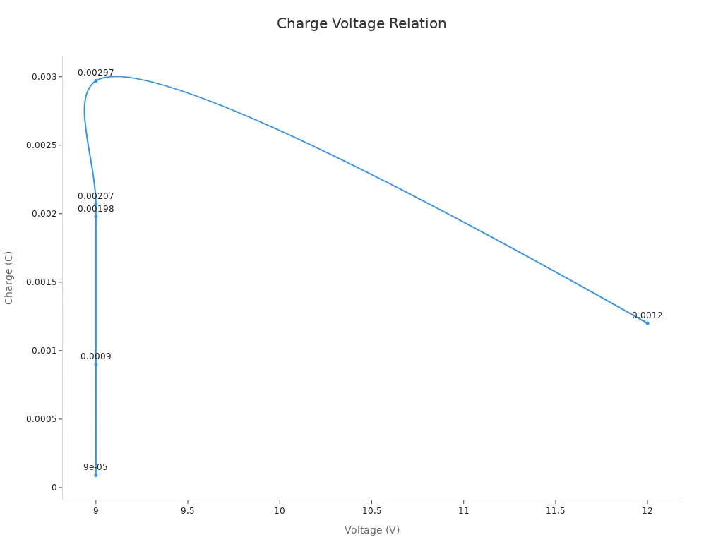
The table below shows how different capacitance and voltage values affect the stored charge:
| Capacitance (F) | Voltage (V) | Charge (Coulombs) |
|---|---|---|
| 0.00001 | 9 | 0.00009 |
| 0.00022 | 9 | 0.00198 |
| 0.0001 | 9 | 0.0009 |
| 0.00023 (230μF) | 9 | 0.00207 |
| 0.00033 (330μF) | 9 | 0.00297 |
| 100μF (0.0001) | 12 | 0.0012 (1.2 mC) |
This table shows that for a fixed voltage, increasing the capacitance increases the charge stored. The relationship is linear. For example, doubling the capacitance doubles the charge at the same voltage.
The unit of capacitance, the farad, is defined so that one farad stores one coulomb of charge at one volt. This direct relationship helps engineers predict how much energy a capacitor can store in a circuit.
Parallel Plate Capacitance Formula
The parallel plate capacitor is a common type used in experiments and electronics. Its capacitance depends on the area of the plates, the distance between them, and the material between the plates. The formula is:
C = ε(A/d)
-
C: Capacitance in farads
-
ε: Permittivity of the dielectric material (measured in farads per meter)
-
A: Area of one plate (in square meters)
-
d: Distance between the plates (in meters)
Permittivity (ε) measures how well a material allows electric fields to pass through. It has two parts: the permittivity of free space (ε₀) and the relative permittivity (εr) of the material. The formula becomes:
C = ε₀ × εr × (A/d)
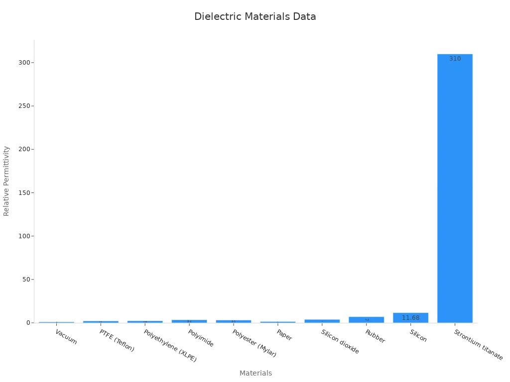
Materials with higher relative permittivity, like titanium dioxide or strontium titanate, allow capacitors to store more charge for the same size and voltage. Engineers choose materials based on the desired capacitance and application.
Note: The dielectric material between the plates not only increases capacitance but also affects how the capacitor behaves at different frequencies and temperatures.
Researchers use Gauss's Law to explain why the electric field between parallel plates is uniform, which supports the capacitance formula. In experiments, scientists keep the plates flat and parallel, and use large plates compared to the distance between them. This setup reduces edge effects, which can cause errors in measurement. By changing the distance between the plates and measuring the resulting voltage and capacitance, they confirm that capacitance increases with plate area and permittivity, and decreases as the distance grows.
Numerical experiments also show that permittivity has a strong effect on capacitor performance. For example, when scientists measure the capacitance of parallel-plate capacitors with different materials, they see that higher permittivity leads to higher capacitance. They also find that fringing effects—where the electric field spreads out at the edges—can make the measured capacitance larger than expected. Careful design and corrections help improve accuracy.
Scientists often use water, saline solutions, or air as dielectrics in experiments. They measure how capacitance changes with different materials and thicknesses, confirming the key role of permittivity in the capacitance formula.
Calculations
Basic Example
Understanding how to use the capacitance formula helps students and engineers solve real-world problems. Consider a simple example with a capacitor in a circuit. Suppose a 10 microfarad (μF) capacitor is charged to 5 volts (V). To find the amount of charge stored, use the formula:
C = Q / V
Rearrange to solve for Q:
Q = C × V
Plug in the values:
-
C = 10 μF = 10 × 10⁻⁶ F
-
V = 5 V
So,
Q = 10 × 10⁻⁶ F × 5 V = 50 × 10⁻⁶ C = 50 μC
This means the capacitor stores 50 microcoulombs of charge. In practical circuits, capacitors smooth voltage, filter signals, and provide quick bursts of energy, such as in camera flashes or blinking LEDs. Students often make mistakes by confusing units or using the wrong formula for the circuit type. Double-checking units and understanding the context helps avoid errors.
In neuroscience research, scientists use a voltage-clamp step method to measure capacitance in neurons. They apply a small voltage step, measure the resulting current, and calculate the charge. Dividing the charge by the voltage step gives the capacitance, which helps them understand how cells store and move electrical signals.
Other Geometries
Capacitors come in many shapes, not just parallel plates. Each shape has its own formula. Here are some common examples:
-
Parallel Plate Capacitor:
C = εr ε0 A / dWhere εr is the relative permittivity, ε0 is the permittivity of free space, A is the plate area, and d is the distance between plates.
-
Cylindrical Capacitor:
C = (2 π εr ε0 l) / ln(b/a)Here, l is the length of the cylinder, a is the inner radius, and b is the outer radius.
-
Spherical Capacitor:
C = 4 π ε0 (ab)/(b - a)Where a and b are the radii of the inner and outer spheres.
The table below shows how researchers use different methods to calculate capacitance for various shapes:
| Geometry Type | Method Used | Key Points |
|---|---|---|
| Cylinders | Method of Moments | Uses subdomains; matches results with known literature. |
| Spheres | Analytical | Uses formulas for separated spheres; provides physical insight. |
| Circular Disks | Method of Moments | Validates results with known data. |
| Rectangular Plates | Numerical | Compares with previous studies. |
| Complex Shapes | Numerical | Models arbitrary planar shapes. |
These formulas and methods help engineers design capacitors for many applications, from electronics to scientific experiments. Using the correct capacitance formula for each geometry ensures accurate results.
Applications
Circuits
Capacitors play a vital role in modern electronic circuits. They store electrical energy by holding charge on two plates separated by a dielectric. This energy storage allows capacitors to smooth voltage changes, shape current flow, and provide quick bursts of energy. Engineers use capacitors for several important functions:
-
Power supply filtering: Capacitors like the 104 type smooth voltage and filter noise, which helps devices last longer.
-
Signal coupling and decoupling: Capacitors separate AC and DC signals, preventing unwanted interference.
-
Frequency filtering: They reduce noise and improve audio quality in sound systems.
-
Timing circuits: Capacitors provide precise timing for oscillators and microcontrollers.
Capacitors also help manage power by storing extra energy and releasing it when needed. In renewable energy systems, they stabilize voltage and improve efficiency. In computers and high-speed electronics, capacitors filter out voltage spikes and keep devices running smoothly.
Tip: Accurate use of the capacitance formula helps engineers design circuits that are stable, efficient, and reliable.
Series and Parallel
Engineers often connect capacitors in series or parallel to achieve the desired total capacitance. The arrangement affects how the circuit behaves. The table below compares the two setups:
| Arrangement | Equivalent Capacitance Formula | Voltage and Current Characteristics | Impact on Circuit Design Effectiveness |
|---|---|---|---|
| Parallel | C_eq = C1 + C2 + ... + Cn | Voltage is the same across each capacitor; total current is the sum | Increases total capacitance and energy storage; voltage limited by smallest rating |
| Series | 1/C_eq = 1/C1 + 1/C2 + ... + 1/Cn | Current is the same through each capacitor; voltage divides among capacitors | Results in lower total capacitance; can handle higher voltage |
For example, two 2 F capacitors in parallel give 4 F. If this 4 F is then placed in series with a 5 F capacitor, the total capacitance becomes about 2.22 F. This flexibility allows engineers to design circuits for specific needs, such as higher energy storage or higher voltage tolerance.
Dielectrics
The dielectric material between a capacitor’s plates greatly affects its performance. By choosing materials with a high dielectric constant, engineers can increase the amount of charge a capacitor can store. Recent experiments show that adding layers like Al2O3 and TiO2 to Hf0.5Zr0.5O2 filmscreates capacitors with high dielectric constants and low leakage currents. These advanced dielectrics meet the needs of memory devices and can withstand billions of charge cycles without losing performance.
Dielectric engineering not only boosts capacitance but also improves reliability and energy efficiency. This makes capacitors more effective in demanding applications, from computers to renewable energy systems.
Tips and Mistakes
Common Errors
Many students and engineers encounter similar mistakes when working with capacitance formulas and measurements. These errors can affect the accuracy of calculations and the performance of electronic circuits. The table below summarizes the most common sources of error, along with their typical uncertainty ranges:
| Error Source | Description | Relative Uncertainty Range (%) |
|---|---|---|
| Dimensional Measurement Errors | Uncertainties in area and thickness measurements of capacitor structures. | 0.7% to 2.4% |
| Depletion Capacitance Errors | Mistakes from not correcting for depletion capacitance, especially in semiconductor devices. | 0.4% to 2.0% (up to 4.4%) |
| Stray Capacitances | Extra capacitance from the shape of probes or circuit parts, such as AFM tips or PCB traces. | Up to 0.72% |
| Permittivity Uncertainty | Inaccurate values for the dielectric constant used in calculations. | ~1.0% |
| Numerical Modeling Errors | Small mistakes from rounding or mesh errors in simulations. | <0.1% |
These errors can combine, leading to a total uncertainty of about 1.4% to 2.8% in capacitance calculations. Small capacitors, especially those below 1 femtofarad, are more sensitive to dimensional and stray capacitance errors. Larger capacitors often show more impact from fabrication and parasitic effects.
Technical studies highlight the importance of accounting for stray and parasitic capacitances in electronic circuits. For example, when measuring operational amplifier input capacitance, engineers must separate the actual capacitance from unwanted effects caused by the test setup and circuit board. Ignoring these factors can distort results and lead to incorrect conclusions.
Best Practices
Experts recommend several strategies to improve the reliability of capacitance measurements and calculations:
-
Always double-check area and thickness measurements for accuracy.
-
Use high-quality instruments to reduce stray and parasitic capacitances.
-
Select dielectric materials with well-documented permittivity values.
-
Apply corrections for depletion capacitance, especially in semiconductor devices.
-
Validate numerical models with experimental data to minimize simulation errors.
Empirical testing under real-world conditions helps improve measurement reliability. Researchers have found that using machine learning models trained on diverse datasets can predict supercapacitor capacitance more accurately. Expert involvement in data selection and model tuning further enhances results. Integrating empirical data with advanced modeling provides a deeper understanding of capacitance behavior in different environments.
Tip: Combining careful measurement, expert analysis, and modern data techniques leads to more reliable and accurate capacitance results.
Understanding the capacitance formula helps students and engineers link physical properties to charge storage and energy use. Designers use this knowledge to select materials and combine capacitors for specific circuit needs. Real-world tests, such as those on wearable supercapacitors, show how calculations support device durability and performance. Researchers confirm that theory matches practice by using machine learning and experimental data. For deeper learning, students can explore electrical engineering courses that cover circuit theory, laboratory work, and computer simulations.
FAQ
What does the unit "farad" mean in real life?
A farad measures how much electric charge a capacitor can store at one volt. Most everyday capacitors use microfarads (μF) or nanofarads (nF) because one farad is a very large value.
Why do capacitors use different dielectric materials?
Different dielectric materials change how much charge a capacitor can hold. Materials with higher permittivity, like ceramics or polymers, increase capacitance. Engineers select materials based on the needs of each circuit.
How does changing the distance between plates affect capacitance?
Decreasing the distance between plates increases capacitance. The plates can store more charge at the same voltage. Increasing the distance lowers capacitance.
Can capacitors store energy forever?
No, capacitors slowly lose stored energy over time due to leakage currents. The rate depends on the dielectric material and the quality of the capacitor.
Written by Jack Elliott from AIChipLink.
AIChipLink, one of the fastest-growing global independent electronic components distributors in the world, offers millions of products from thousands of manufacturers, and many of our in-stock parts is available to ship same day.
We mainly source and distribute integrated circuit (IC) products of brands such as Broadcom, Microchip, Texas Instruments, Infineon, NXP, Analog Devices, Qualcomm, Intel, etc., which are widely used in communication & network, telecom, industrial control, new energy and automotive electronics.
Empowered by AI, Linked to the Future. Get started on AIChipLink.com and submit your RFQ online today!


